Why grid visibility matters
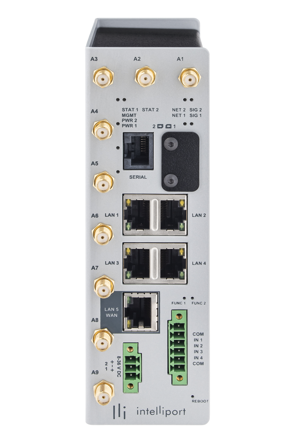
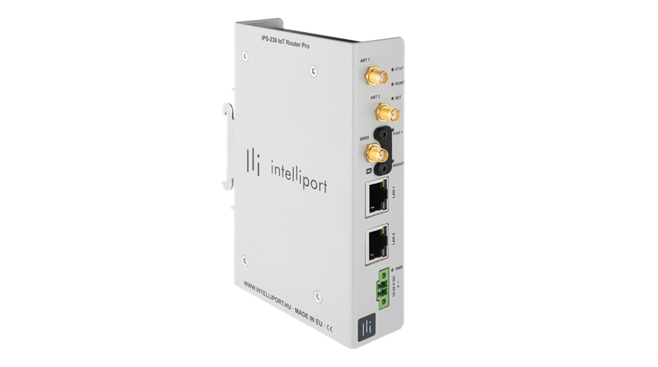
As decentralised, weather-dependent generation expands, reverse power flows, local constraints and voltage issues may become more frequent across MV/LV networks. Substation digitalisation can provide a shared data and communications foundation for monitoring these conditions consistently.
The objective is not another isolated measuring point it is an operable data path from field signals to central supervision, with clear responsibility and security boundaries
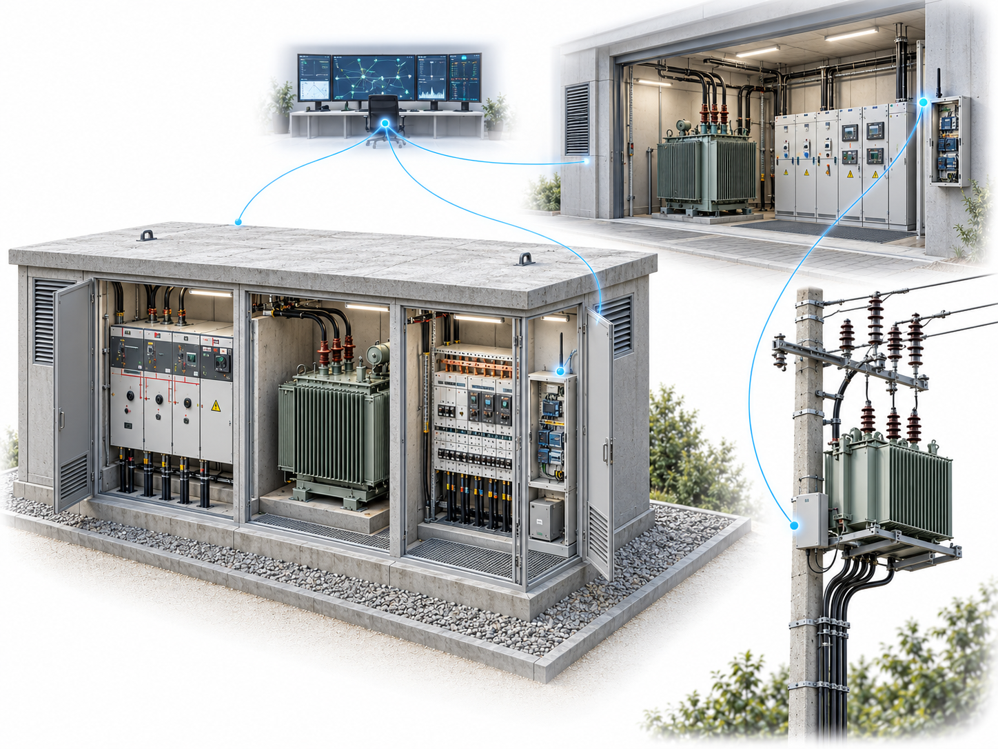
One data path with controlled boundaries
The first measurement use case is LV-side voltage monitoring. The same infrastructure can later provide the foundation for connecting further field devices and central systems.
Measurement point
Three-phase LV voltage monitoring through an instrument circuit designed and protected for the local electrical installation.
Field connection
A connection matched to existing equipment and protocols, such as RS-485 and Modbus RTU where confirmed by the site survey.
Substation edge
Data polling, validation, event generation, local buffering and secure forwarding towards the central environment.
Mobile WAN
Mobile connectivity selected for coverage and availability objectives, with a backup path and managed failover where required.
Central layer
Device lifecycle, configuration, monitoring and data reception; the boundary of HES, SCADA or DMS integration remains a separate design decision.
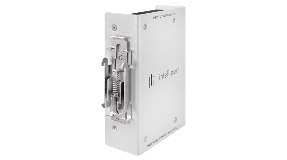
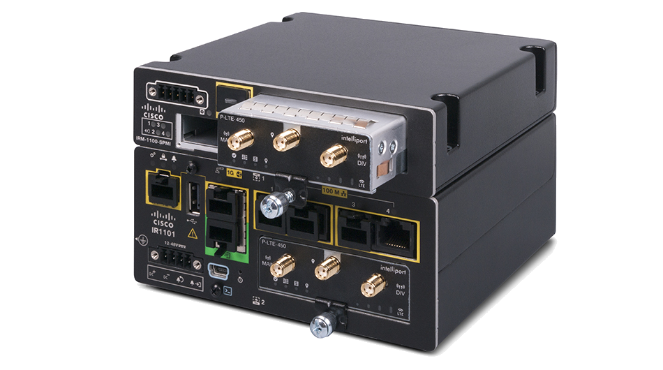
Interfaces, protocols, mobile technology and central integration must be matched to the existing substation infrastructure for each project.
Six capabilities of the communications foundation
Industrial reliability
Connection recovery, watchdog functions and operating conditions verified for the substation environment.
Communications resilience
Primary and backup connectivity selected for project availability objectives, with measurable connection quality.
IT/OT segregation
Network zones, permitted data flows, and separation of administrative and operational traffic.
Security foundations
Device identity, encrypted communications, access control and auditable changes under the approved security model.
Controlled deployment
Approved configuration profiles, automatable registration and a verifiable, phased rollout.
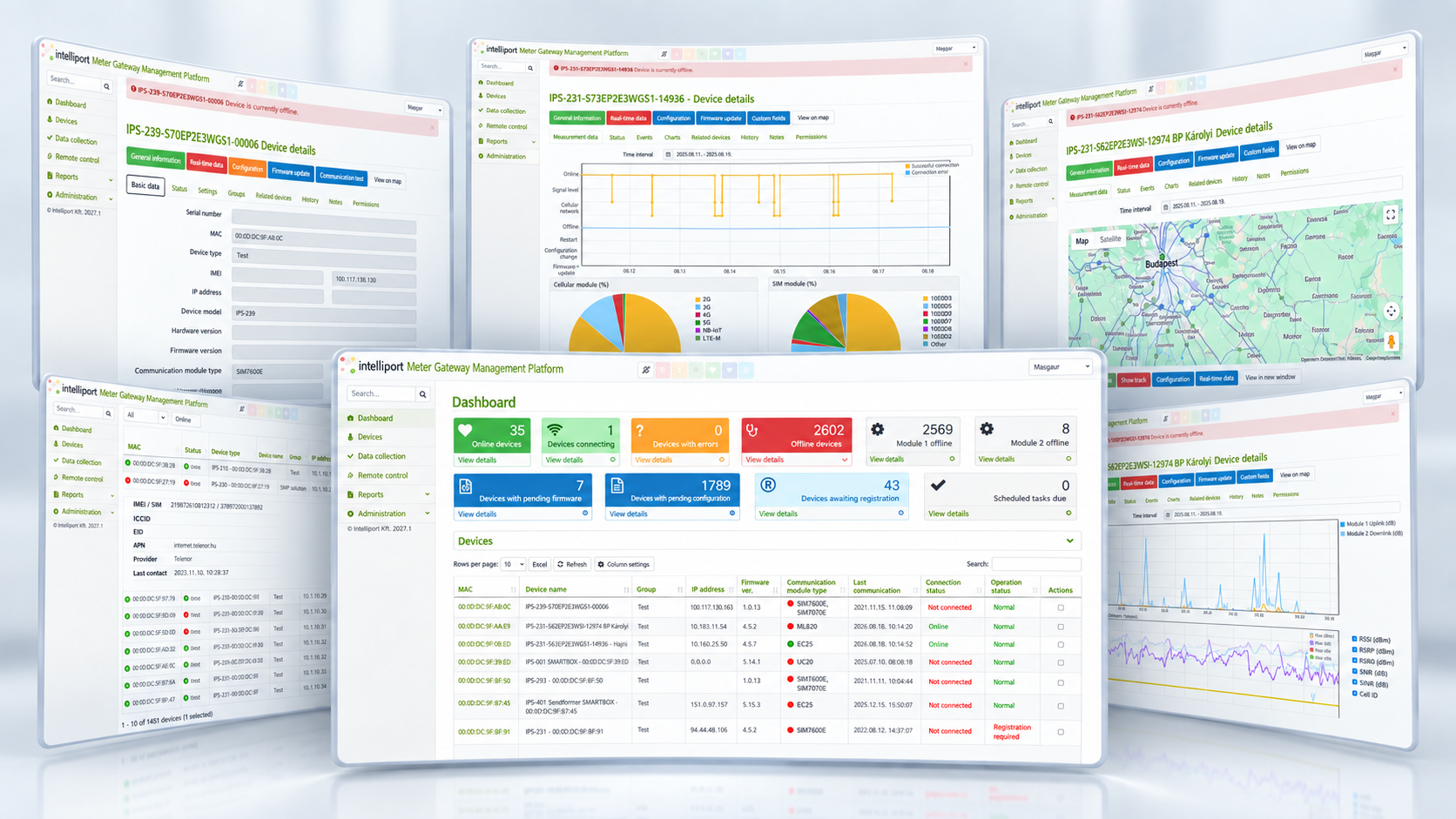
Central management
Configuration and firmware lifecycle, status monitoring, alarms, logging and alignment with central processes.
First phase: three-phase LV voltage monitoring
The first phase is intended to make voltage conditions visible at scale without introducing full energy metering or automatic control. Sampling, thresholds and event handling must be matched to the grid objectives.
Phase voltages
Voltage values for each phase at the approved sampling and transmission frequency.
Minimum and maximum
Periodic extremes that help compare daytime and evening deviations.
Phase loss and imbalance
Event indications to help screen affected LV areas and support fault investigation.
Communications status
Meter availability, field communications and edge-device status interpreted alongside measurement data.
Measurement scope of the first phase
- phase-to-neutral and, where required, phase-to-phase voltage;
- frequency, phase loss and imbalance;
- threshold, device and communications events.
Not included by default
- current, power and full energy metering;
- determining transformer loading;
- automatic grid intervention or control.
Security and compliance boundaries
Security is not a single product feature. It is a shared design concern across the data path, operating processes and assigned responsibilities.
- IEC 62443-4-2 or an equivalent level may be specified as a project requirement; this does not by itself demonstrate certification of a particular product.
- The solution can support NIS2 readiness but does not constitute organisational compliance on its own.
- Remote access and control are not assumed. They must be designed within an approved access-control, logging and operating framework.
- Boundaries around field protection and control functions must be established with the existing substation systems.
From survey to controlled rollout
Architecture and site survey
Document interfaces, protocols, mobile coverage, IT/OT zones, central integrations and operating responsibilities.
Pilot and validation
Validate connectivity, device management, the security model and voltage monitoring at selected sites.
Phased rollout
Use approved templates, central device management, and predefined acceptance, handover and rollback conditions.
Later extensions subject to a separate decision
The shared communications foundation can support further measurement and integration tasks, but these are not automatically part of the first phase.
- connecting additional meters and sensors;
- extended power and energy monitoring;
- HES, SCADA and DMS integration;
- local data processing and more advanced event logic;
- remote or automatic control following separate security and operational approval.
Where joint design begins
- Which substation types, field devices and protocols are in service?
- Which measurements and events are required in the first phase?
- What mobile coverage and availability objectives can be verified at the sites?
- Where are the IT/OT zone boundaries, and which data flows can be permitted?
- Which central systems must be connected, and who owns data quality?
- Which pilot criteria must be met before rollout begins?